In the previous week of Nand2Tetris we created logic gates which perform simple boolean operations Not, Xor, And etc.
But what do these have to do with computers? Might come to your mind.
Well in this week we’ll understand how those simple gates are actually the building blocks of how computers in the world work.
Adding 2 Numbers:
To give a holistic view, I’d like to propose an example of how we can add 2 numbers together using the logic gates. (Sound weird right?)
Before we can do that you’ll need some understanding of how binary & positional number systems work.
Positional Number System:
So when you say one-thousand-four-hunderd-and-three the number “1403” comes to mind. Why don’t we read it as one-four-zero-three? This is where positional number system come in where the position of the number represents its value. Let’s explore this even more:
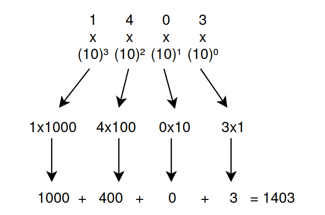
Hopefully the image explain the concept clearly. In positional number system the value of a digit is represented by it’s position. So every other digit will have a value exponentially greater than the last.
Another question that might arise is: Why are we raising 10 to powers and not some other number? Well it because we’re currently using base 10 decimal system numbers (0-9) in total 10 numbers.
So now onto Base 2 (Binary): Like Base 10 Base 2 is also positional number system and it works as following:
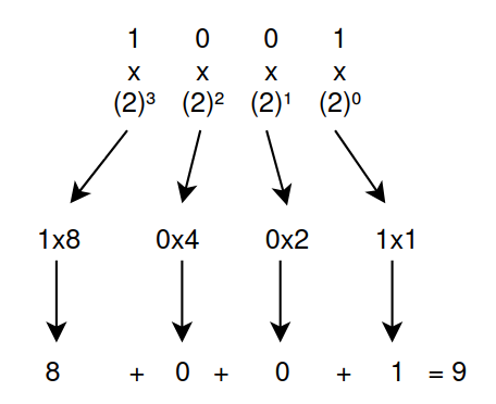
As before we have some numbers, but the difference is we only have 2 symbols at our disposal 1 and 0 instead of 0-9 (That’s Binary!). Using the same principles as before raising 2 to powers this time we can translate binary into a base 10 integer as shown in the image.
Equipped with this knowledge we can move on to understanding how to add 2 binary numbers:
In order to add binary number we need to learn something called the 2’s complement. If you’re unaware about this technique I’ll highly recommend you to check out Organic Chemistry Tutor’s video: https://youtu.be/sJXTo3EZoxM?t=363
It explains the topic so eloquently and with visual aid, (so you don’t have to stare at a wall of screenshots and text LOL)
So once you’re aware about binary number system, addition we can move on to making a logic gate which will do that for us:
The thought process:
Lets look at the inputs and outputs when adding two bits together in binary. their possible permutations will be as:

This is how adding 2 bits together will look like with all possible permutations with sums and carry bits. Do you recognize a pattern here which matches with the gates we previously built? It’s the AND Gate for the carry and the XOR gate for sum. And this is how a Half-Adder chip is built.
Following this we can combine 2 Half-Adder chips together to get a full Adder-Chip which can add 3 bits instead of 2!
Constructing an ALU:
With the previous example it was demonstrated how we can derive different functions using logic gates. Now we can construct an all purpose ALU chip. The ALU can perform different functions such as: Addition, Subtraction, Bit-Wise operations etc.
The truth table of the ALU we will be building in Nand2Tetris will look like:
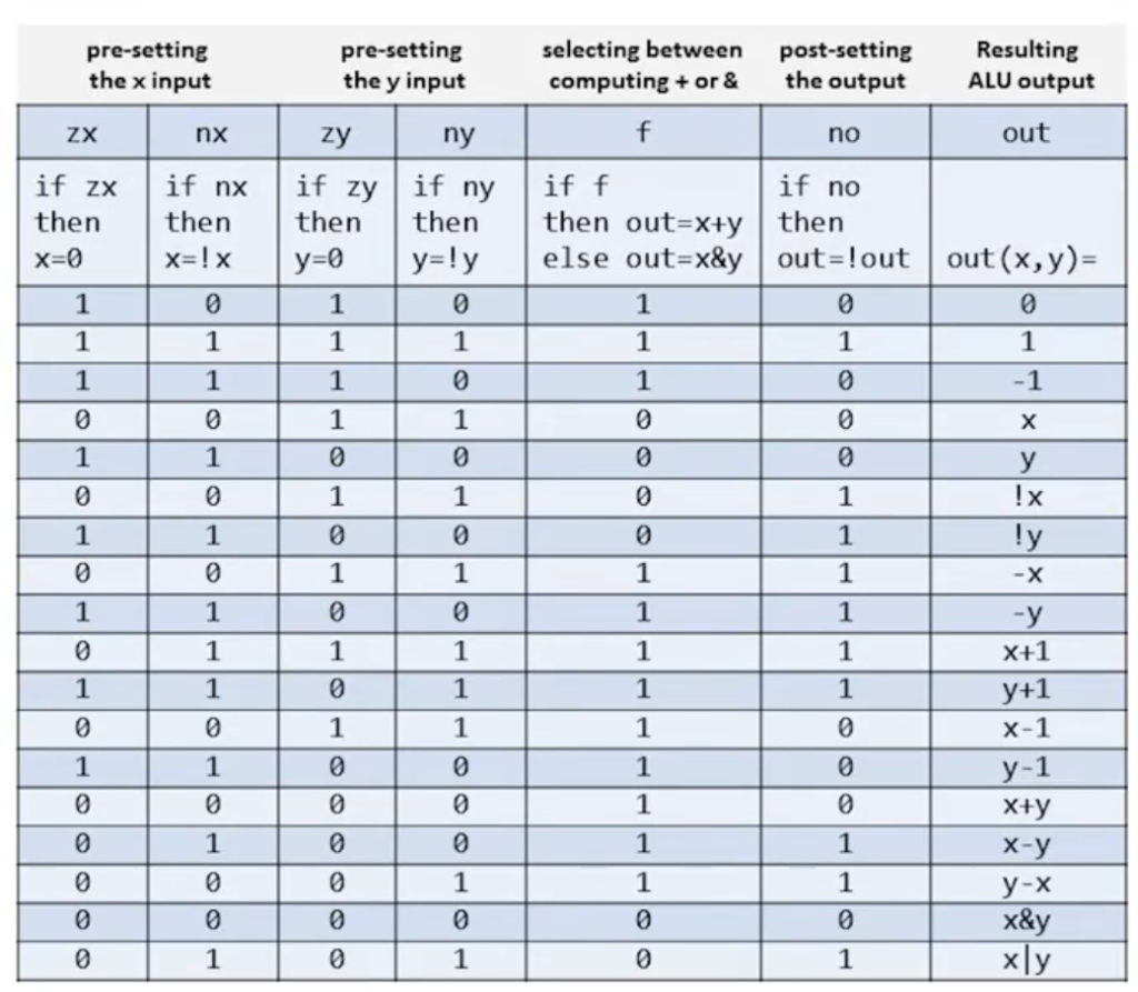
The first 6 columns here are the inputs which will be provided to the the ALU chip to compute the respective output on a given input. However the interesting thing is that multiple control bits can be set in a single use. For example: if the zx and no bits are set we’ll first set the x input to zero and then NOT it so the final output for x would be 1.
I could think of how to construct the functionality for the for the zx and no operations. However what I couldn’t figure out was how to do them both one after another.
Why? Well because HDL is not like a programming language it doesn’t execute one line after another. It simulates hardware where every chip is engaged all at once. So how can you perform one operation after another when everything is going to happen all at once? (Referring to a time unit obviously in a physical environment electricity itself will take time to reach one chip after another)
This question kept me thinking for a few days. One day I was almost asleep when I suddenly realized that if I can’t sequentially operate on one piece of data I can just pre-compute the output. That way I can choose between what I need based on the control bit. How can I do that? Well we built a multiplexer chip in the last week which performs just this function. (After this realization I jumped out of my bed and noted this down on my board and seemed like I had solved my issue)
The last 2 part of the puzzle were the zr and ng bits. Which tell information about the output, if the output is zero zr bit will be 1, if output is in negative ng bit will be zero.
zr:
The zr bit was easy. Since zero is represented by 0 in binary you just OR every bit of the output with each other. If the output is 0 that means the the input (the ALU output) was also zero.
ng:
The ng bit was a bit more tricky (no pun intended), but after revising how binary negative integers work. I found out that negative number in 2’s complement all start with 1, so you can just check the last bit in the output.
Conclusion:
So there we have it. We’ve successfully constructed an ALU out of logic gates. Seems pretty fascinating how true/false expressions can create something so functional. One thing about computers that always surprises me is their simplicity. Beneath all the heavy abstractions is a single chip essential to everything in use.
I have purposely not included all the code that I wrote. As the purpose of this blog is not to provide a walkthrough of the entire project. But to share what things challenged me during the project and explain my through process and the approaches I took to get to the solution. The intention for writing these blogs is to provide alternative problem solving approaches.
Leave a Reply