Recap:
So far, we’ve created elementary & composite gates, an ALU and Memory holding chips for the project. Which essentially gives us all the building blocks to build a functioning CPU which combines the functionality of all of these.
Week 4:
For Week 4 we’ll be taking a detour from the combining and creating chips. Week 4’s focus will be to get us familiarized with the assembly language.
Assembly Language is the a symbolic way to represent machine code 0s and 1s. Using symbolic wrappers for 0’s and 1’s makes it much, much easier to write and read machine code.
Two questions might be coming to your might right now:
- How do we execute machine language?
- How does machine language work?
To answer the first question. To execute machine language we’ll create the CPU in which we’ll feed the machine language and it’ll perform magic. How do we make a CPU? Well that’ll be discussed in the next week for now we need to understand assembly and machine code before building the CPU. It’ll be much easier to architect a CPU after we understand and comprehend what the CPU is supposed to do.
For the second question. Once we create the CPU we’ll automatically understand how machine language interacts with it. So for now we need to focus on understanding assembly. We’re essentially shifting out learning approach this week instead of from going bottom to up we’re going up to bottom.
Assembly:
At first I was a little intimidated and thought it might take me quite a lot of time to grasp assembly. I knew it had to do something with registers, but didn’t knew much else about it.
Nand2Tetris really did a great job about demonstrating how assembly works. And so far it doesn’t seem so complicated. (At least the custom implementation in the course)
So how does it work? You essentially move data between registers and perform operation on the data which effects the flow of the program.
Instead of rambling about complexities of assembly let’s first see an example so we have something to reference to when learning about it:
D+1
This is a simple line of assembly which adds 1 to a value present in the register. It’s not of much use on it’s on until combined with other instructions.
In order to understand assembly further we need to understand the different types of instructions and registers it has.
Registers:
We will have 3 kinds of special registers available to us.
– Address
– Memory
– Data
Address:
The address register represented by A stores the value of the currently selected memory register. So essentially if we the computer wants to access a specific part of a memory we need to have some place where it look up the address. A computer can look for such an address in the address register.
Memory:
The memory register reflects whatever the selected memory register holds. It’s not the address of a register, but the contents of the register.
To give an analogy about the address and memory register. The Address register is a box in which we contains an address to a house. And the Memory register shows us what the house contains.
Data:
Data register is just a simple address to which we can write and read data from. It’s denoted by D
Instruction Types:
We have 2 types of instructions available to us in assembly of Nand2Tetris.
- Type A
- Type C
Type A:
An instruction of Type A is known as an addressing instruction. Type A instruction is used to select a specific register from memory. Why? Whenever we want to operate on a specific register in the memory we need to select it before hand.
For example if we want to operate on memory register number 32 we first would need to address it. The instruction to do that will look like:
@32
Once we’ve selected this memory register. The register M would output whatever the @32 contains and A register would simply be the address which in this case would is 32.
Type C:
A Type C instruction is a little more complex than a Type A instruction. Type C instruction is primarily made up of 3 parts:
- Destination (Optional)
- Computation
- Jump Condition (Optional)
An instruction would look something like this:
M=M+1;JNE
Let’s explore each of the fields in detail.
Destination:
Destination field refers to where we want the output of the computation to be stored. This is also why this field is optional we can compute something but not store it’s output any where. The possible destination are:
- M
- A
- D
Computation:
The computation part might be the most complex out of the others. It refers to what kind of operation we want to perform. We can only perform operation predefined as illustrated by this image:
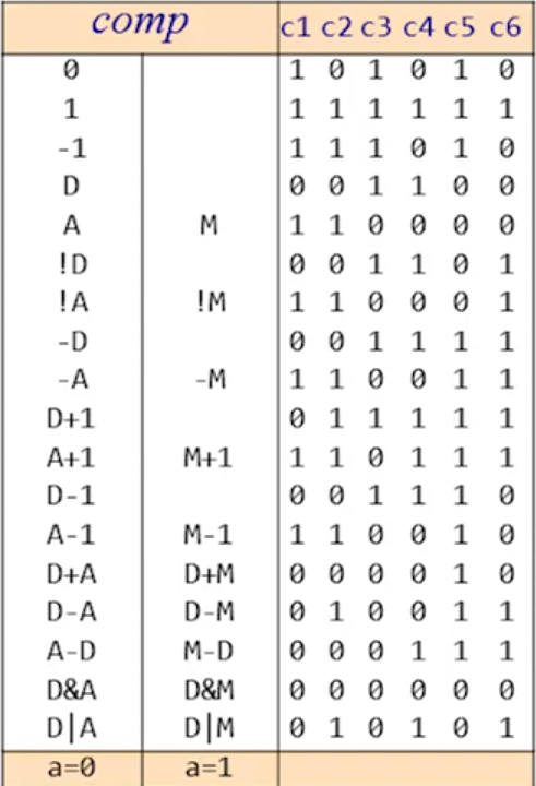
The instructions in the first 2 columns are the instructions we can can use for the computation field. Do the instructions look familiar to you? Yes, these are the same instructions which are performed by the ALU. So you can already guess when we construct the CPU this functionality will be performed by the ALU.
Jump:
Jump field is quite fun. It essentially makes the program execute at another specified point.
In the assembly the execution of the program is sequential. Which mean that execution is performed line by line just like in any regular programming language.
If you have even some minor experience with programming you should be aware about the if statement. It allows you to check if some defined condition is true of false and then take an action based on that evaluation. If statements are used to disrupt the program for example:
If variable_a = 10:
Do X
Otherwise:
Continue
This is just some pesudo-code example to drive the point home. So to achieve this kind of functionality in assembly we will use jump statements.
So now let’s jump to understanding the jump instruction (Hah pun intended). First here are all the possible jump instructions (And what they’ll look like in machine code):
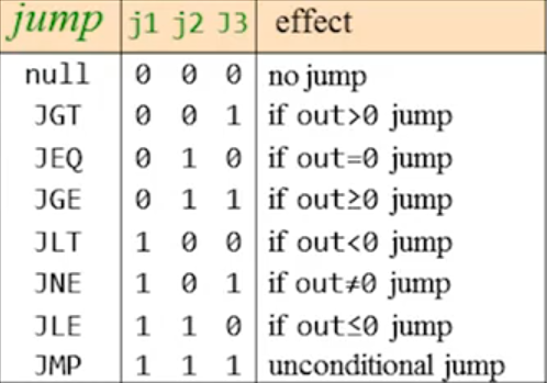
Let’s try to understand the JEQ instruction. It’s an abbreviation of Jump (if) Equal to and it does precisely that. When we use JEQ instruction we want the program flow to jump if the output is equal to zero. But now the questions that should be coming to mind are:
- What output?
- Jump to where?
Let’s tackle that the what first. Well it’s simple actually the output refers to the computation instruction if the output of the computation performed is equal to zero the program will jump.
Now on to the where. Well that’s actually quite interesting. The program jumps to the line number same as the currently selected memory register. For example if we currently have selected the memory unit @31 the program will jump to line 31. So if we want our program to jump to specific line we first need to select a memory register of the same number. It seems weird but it’ll make sense once you construct the CPU.
Program Flow:
Let’s discuss a little about how the program flow works. When executing a program in assembly the flow of executions will simply go line by line. Unless a jump statement is triggered.
Some example programs:
Let’s try to first do a simple thing try to add 2 numbers:
@0
D=M
@1
D=D+M
@2
M=D
In this example we add the numbers present in in Register 0 and Register 1 and add the sum to Register 2. Quite neat huh?
Just let that sync in we built this thing with just simple Nand gates and now we can do this sort of stuff with it. Given it’s not much it’s still amazing comparing we start from true/false.
Devices:
Time to tackle the concepts of devices. In Nand2Tetris we have certain devices available to us which allows us to provide input and get output from the computer we’re building. These include:
- Keyboard
- Screen
These devices allow us to interact with the computer.
As the project is virtual the devices listed above will also function virtually.
So let’s dive into how the we can perform I/O operation via these devices:
Keyboard:
The keyboard device will function very simply. When a key is pressed on the virtual keyboard connected to our computer. Whatever key we press will be reflected in register no. 24,576. So we can access this register to receive input from user.
But our registers can only store numbers! How will we input alphabets via the keyboard?
Well, to tackle that we create another abstraction, yay! We simply assign different numbers to different characters which the running program can interpret as such.
For example at a low level this character A is just the number 65 to a computer. So we can assign different numbers to different symbols we want at higher levels but at low level it’s all numbers.
In-Fact there already exists a universal mapping scheme which maps numbers to symbols. It’s called ASCII – American Standard Code for Information Interchange. Here’s how it looks like:
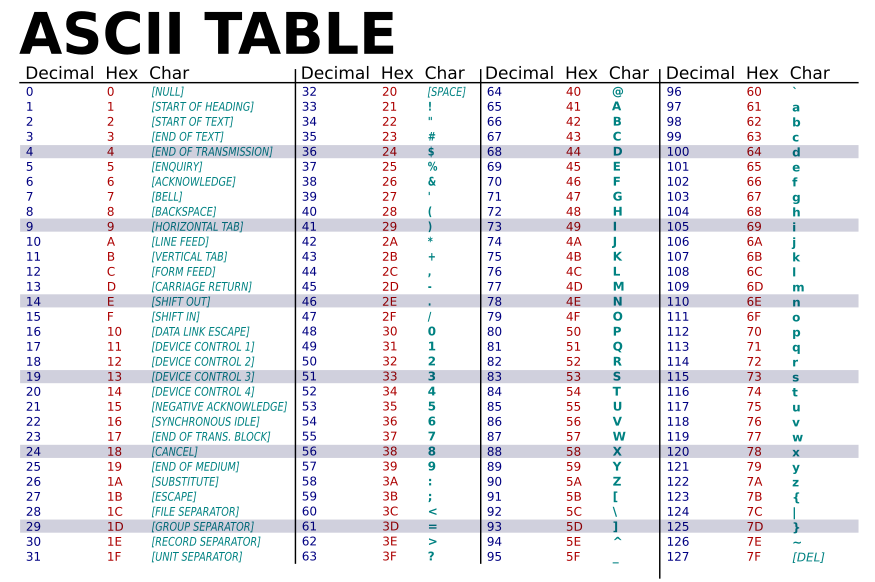
There also exist other Unicode which is also used to represent different language symbols and emojis. (However that’s out of scope right now, so we’ll not dwell into it much further)
Screen:
The functioning of the screen is also not much complex. First let’s clear a very basic concept of pixels. A screen device is made up of many many tiny dots called pixels even the one in front of you!
Think of it like combining a bunch of led bulbs together. You combine and combine until you can create a picture out of those bulbs that’s essentially a screen. The bulbs here corresponds to a pixel in this analogy.
Now in regular screens you usually can have RGB values to dictate how the pixel should look like to create colored picture. However in Nand2Tetris we’ll use a simpler screen in which a pixel can either be black of white. But the core principle remains.
Now onto how we can actually display information onto the screen. For that we allocate a rage of registers in memory and map them to different pixels. So if we change the value of X register the output will be reflected by the Y pixel from the screen.
In order to understand the mapping we need to understand the concept of rows and columns.
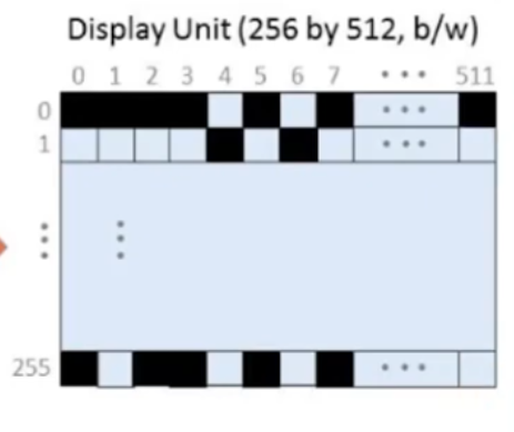
Here’s how the screen will look like and it’s dimensions (Referring to pixels).
Now onto some nitty gritty details. First let’s define the range of registers we need to allocate to handle every pixel of the screen. Since there are 512 x 256 pixels that equals to: 131072. So we have a total of 131072 pixels on the screen and each require one bit allocated to it to function.
Determining the number of registers required to allocate for the interaction with the screen is quite simple from here. Since a register can hold 16 bits we can divide 131072 by 16 to get the number registers required. 131072 / 16 = 8192, so we need 8192 number of registers to manage every pixel on the screen via memory.
The concept of rows and columns is quite straight forward, however it will come in handy just about now. The horizontal lines are called rows while vertical lines are called columns.
32 registers represent a single row on the screen (16 x 32 = 512 exactly the number of pixels in one row) . If we want to manipulate a bit on the screen we do it by it’s column and row number. (Column and row numbers are mapped as demonstrated in the above picture)
So now what if we want to manipulate a very specific pixel on the screen let’s say pixel number 513. How can we determine what bit number in what register number will we need to manipulate from the 8192 registers.
Practical:
If we want to manipulate the pixel 513 first we figure out it’s row and column number which is c:1 and r:2.
Next we need to figure out in which register this bit resides for that we can use the formula:32 * row + col/16
Let’s try that for our case:32 * 2 + 1/16 = 64 We ignore the remainder for this and only care about the quotient
Now we know the bit mapped to 513 pixel resides in register number “64”.
To figure out what bit we need to change in that particular register we use the formula:col % 16
Let’s try that for our case:1 % 16 = 1
So we need to manipulate the second bit in the 64 register (cause there’s also zero which is the first bit) to change that particular bit.
Conclusion:
So after learning how the assembly language is supposed to work new questions should be coming to mind. As we didn’t build the hardware is capable of running this, how will it be made? And what about the screen? If I want to make a screen myself how can I make that IRL? The first one will be tackled in week 5 of Nand2Tetris where we build a complete CPU which can operate on instructions.
Another thing I would recommend is to experiment around with the program exercises given. Like adding to numbers, try to construct them before the instructors provide you with any hints. This will help you get into the thinking mode to be able to build programs in assembly.
The next week is going to be the most fun out of all. Since that’ll be the final part of Nand Hardware you build.